In this project, we will learn how to write data to MIFARE 1K RFID Card using RC522 RFID Reader/ Writer Module. This is useful if you want to place custom data relating to the label like student info or employee details.
We will use Arduino as the host controller to interface with RC5 22 RFID Module and write data to RFID card. I previously made a tutorial on how to interface RC5 22 RFID Module with Arduino. Check out that tutorial before proceeding further as there are some basics related to RFID Communication, MFRC5 22 IC, RC522 RFID Module and more.
A Brief Look at Memory Map of MIFARE 1K Tag
If you upload the’ DumpInfo’ example and open the serial monitor, Arduino will engrave all the contents of the MIFARE 1K RFID Tag on the serial observer after checking it properly.
It is very important to understand the remembering layout of the RFID Tag as we will know what is the significance of each memory location, what memory locations are earmarked and what sites are free to use for collecting used data.
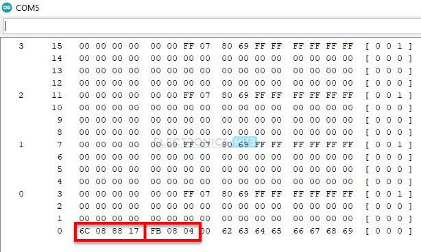
The following portrait is a screen shot of the serial observe yield of’ DumpInfo’ example. Let we are currently analyze this.
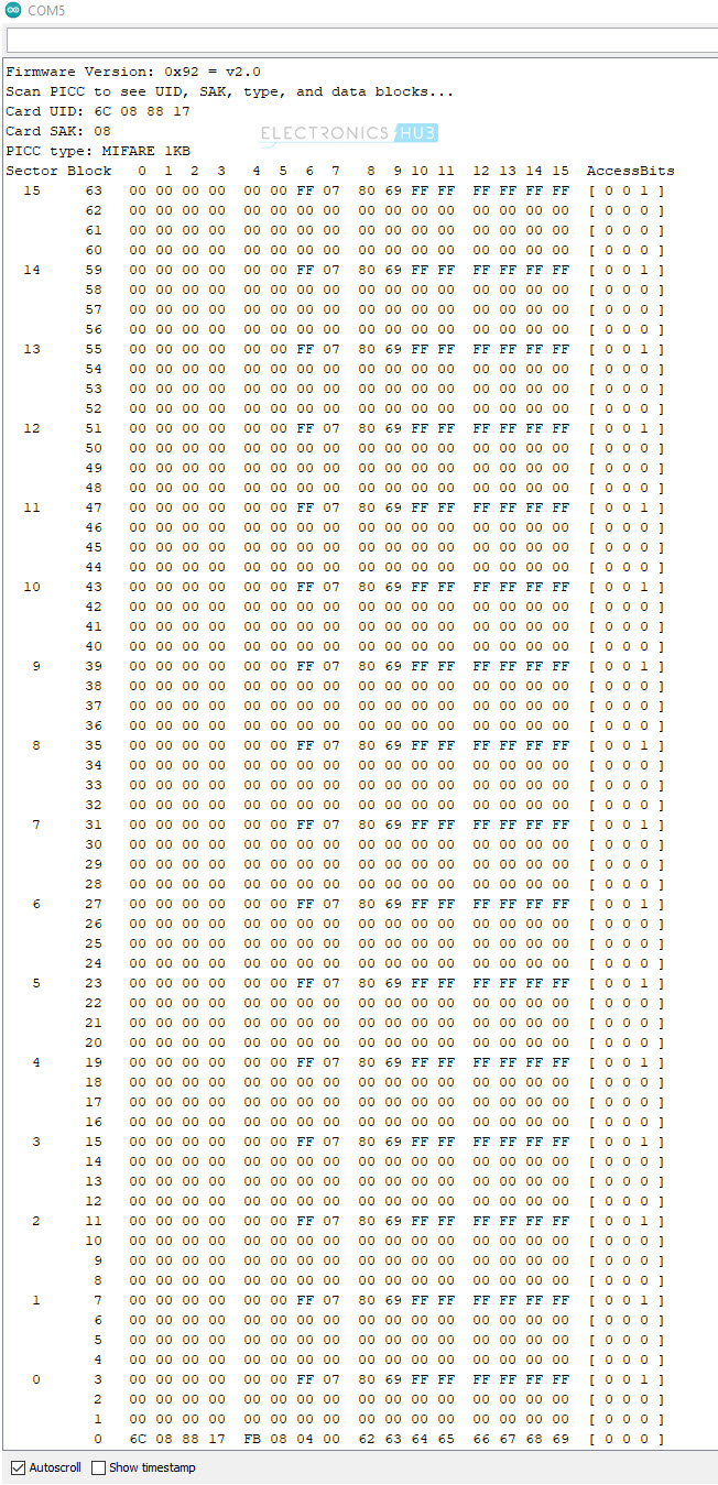
Analyzing Serial Monitor Output
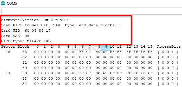
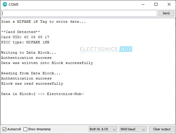
The first route shows the firmware version of the MFRC5 22 IC. In such cases, the result is 0x92. Now,’ 9’ stands for MFRC5 22 IC and’ 2’ stands for software version 2.0. After scanning the RFID Card, we get the UID, SAK and Type of RFID tag.
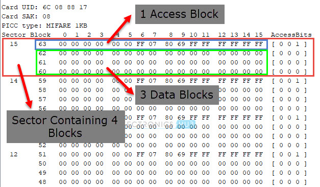
In this case, the UID is’ 6C 08 88 17 ’, SAK is’ 08 ’ and the type of card is MIFARE 1K.
Next, you can see the actual memory dump of the MIFARE 1K Tag. A ordinary MIFARE 1K RFID tag has 1K Byte of reminiscence organized into 16 Sectors( Sector 0 to Sector 15 ). Each Sector consists of 4 Blocks.
Understanding remembering Map of MIFARE 1K Tag
For example, Sector 0 has Blocks 0, 1, 2 and 3. Sector 1 has Blocks 4, 5, 6 and 7 and so on and finally Sector 15 has Blocks 60, 61, 62 and 63. Each Block can store 16 Bytes of data.
NOTE: This numbering is just to understand the recognition layout.
So, 16 Sectors* 4 Blocks* 16 Bytes= 1024 Bytes= 1K
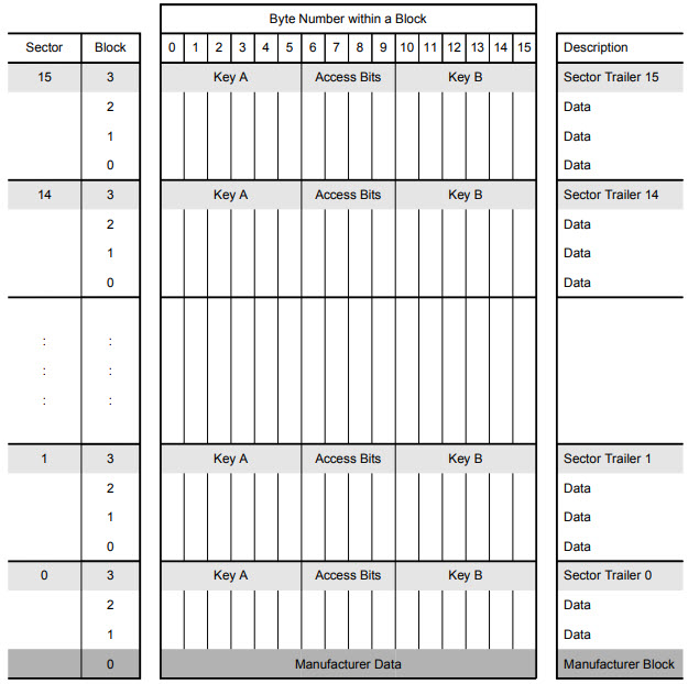
Block 0 of Sector 0 is reserved for storing Manufacturer Data. Usually, this Block contains 4 Byte UID( Unique ID) in case of MIFARE 1K Tags( and likewise MIFARE 4K, MIFARE Mini tags from NXP ). Advanced Tags like MIFARE Plus, MIFARE Ultralight, MIFARE DESFire consists of a 7 Byte UID.
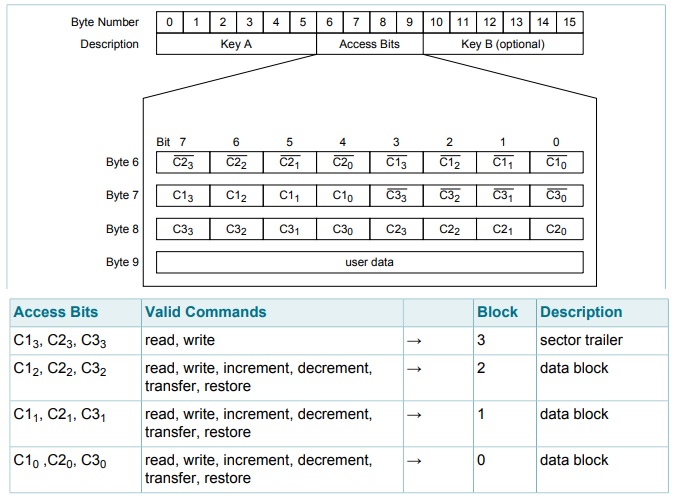
Each Sector consists of three Data Blocks, which can be used for storing user data. The last-place Block of each Sector i.e ., Block 3 in case of Sector 0, Block 7 in case of Sector 1 and so on is known as Sector Trailer.
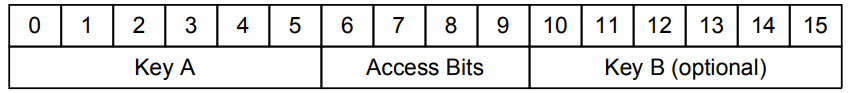
As there are 16 Sectors, there are currently 16 Sector Trailers. Each Sector Trailer consists of the following information 😛 TAGEND
A obligatory 6 Byte Key A. 4 Bytes for Access Bit. Optional 6 Byte Key B( if not used, data can be accumulated ).
NOTE: Byte 9 in the’ Access Bits’ region is available for user data.
NOTE: All sectors have three data blocks and one sphere trailer except area 0. It has one block( Block 0) reserved for Manufacturer Data. So, Sector 0 has two data blocks and one sphere trailer.
The Access Bits in the Sector Trailer determine the access conditions for all the blocks of a Sector. 3-bits are needed for specifying access conditions for the three data blocks and the sector trailer. The access circumstance includes Read, Write, Increment, Decrement, Transfer and Restore.
With all this information, we can conclude that, you can store 47 Bytes of Data in a MIFARE 1K RFID Data. Let us now see how to Write Data to RFID Tag using Arduino and RC522 RFID Module.
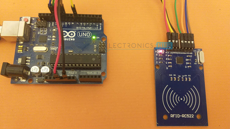
Interfacing RC522 with Arduino
Even though MFRC5 22 IC fundings three types of Serial Communication; UART, SPI and I2C, the SPI Interface is the fastest and most common. The following likenes shows the pinout of RC522 RFID Module.
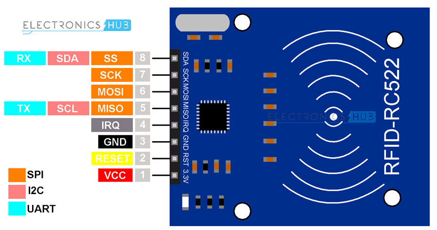
For reliable communication between Arduino and RC522, cause us use the Hardware SPI Pins. The following table shows the connections between Arduino and RC522 Module.
RC5 22 RFID Module
Arduino UNO
VCC
3.3 V
RST
7
GND
GND
IRQ
—
MISO
12
MOSI
11
SCK
13
SS
10
Components Required
Arduino UNO RC522 RFID Reader/ Writer Module MIFARE 1K RFID Tag Connecting Wires
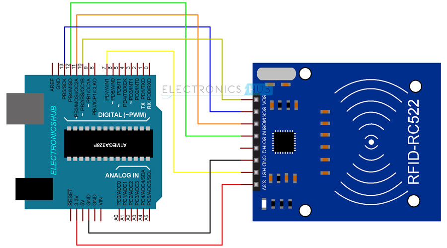
Circuit Diagram
The following portrait shows the connections between Arduino and RC522 RFID Module.
Write Data to RFID Card
I wrote a simple program in which I write data to 1 Block( Block 2) and crowd it wholly. This means, the length of the data should be 16 Bytes.
System
The Arduino code for writing data in to MIFARE 1K RFID Tag is given below. I observed the system so that you can understand it easily.
Code
Conclusion
A simple demonstration on how to Write Data to RFID card expend RC522 RFID Reader/ Write Module and Arduino UNO. You learned the remembrance layout of MIFARE Classic 1K RFID Tags, memory locations feasible to write data and also write some random verse to an RFID Card.
The post How to Write Data to RFID Card apply RC522 RFID and Arduino ? sounded first on Electronics Hub.
Read more: electronicshub.org


Recent Comments